- Board: Arduino Mega or Mega 2560
- Processor: ATmega1280
- Port: COM3 (this property can be determined in the device manager)
Download source code/project files (Visual C# Express 2010)
You'll obviously need a few things before doing this.
- A digital SLR camera (I used a Canon Rebel XTi)
- A remote shutter release (I used this cheap thing, but it will depend on your camera. I image the same basic principles apply to different cables.)
- 2 2N2222 transistors
- This wonderful page right here!
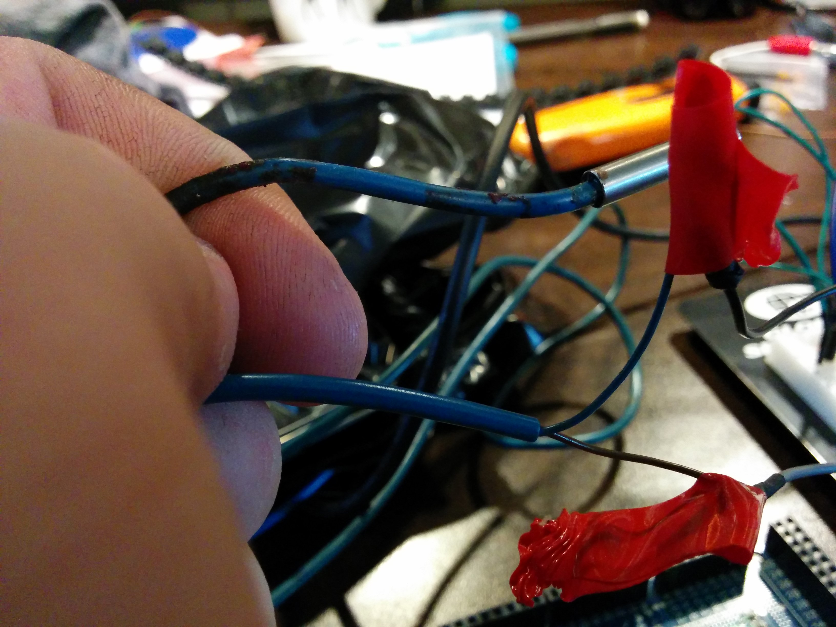
First thing we need to do is chop the remote shutter release cable up. Yup. Cut it open and you'll find three differently coloured wires inside - red, yellow (or green), and white. Red is your shutter, yellow/green is your focus, and white is the ground.
I used 4 different digital output pins here - one for the focus, one for the shutter, one for the focus LED (lights up after focusing) and one for the shutter LED (lights up for a second after taking a picture)... the point of the LEDs was so I could test the C# program without running the camera all the time because I was lazy and was working with a dying battery. Hey, at least I'm honest, okay?
Here's my Arduino code:
#define FOCUS_PIN 51
#define FOCUS_LED 50
#define SHUTTER_PIN 53
#define SHUTTER_LED 52

void setup()
{
  pinMode(FOCUS_PIN, OUTPUT);
  pinMode(SHUTTER_PIN, OUTPUT);
  digitalWrite(FOCUS_PIN, LOW);
  digitalWrite(SHUTTER_PIN, LOW);
  pinMode(FOCUS_LED, OUTPUT);
  pinMode(SHUTTER_LED, OUTPUT);
  Serial.begin(9600);
}

void loop()
{
  int cmd;

  while (Serial.available() > 0)
  {
	cmd = Serial.read();

	switch (cmd)
	{
	case 'f':
	  {
		digitalWrite(FOCUS_PIN, HIGH);
		delay(800); // May want to adjust this depending on focus time
		digitalWrite(FOCUS_PIN, LOW);
		digitalWrite(FOCUS_LED, HIGH);
		delay(1000);
		digitalWrite(FOCUS_LED, LOW);
		break;
	  }
	case 's':
	  {
		digitalWrite(SHUTTER_PIN, HIGH);
		delay(2000); // May want to adjust this depending on shot type
		digitalWrite(SHUTTER_PIN, LOW);
		digitalWrite(SHUTTER_LED, HIGH);
		delay(1000);
		digitalWrite(SHUTTER_LED, LOW);
		break;
	  }
	default:
	  {
		Serial.println("ERROR!");
	  }
	}
  }
}
Truth be told, I got the majority of this code from this page over here. Very helpful page!
My C# program is very much like the one that I was playing with in my arduino tests earlier.
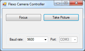
My C# code is very simple, I just use serialPort.Write("s"); when the user clicks the "Take Picture" button and serialPort.Write("f"); for the "Focus" button.
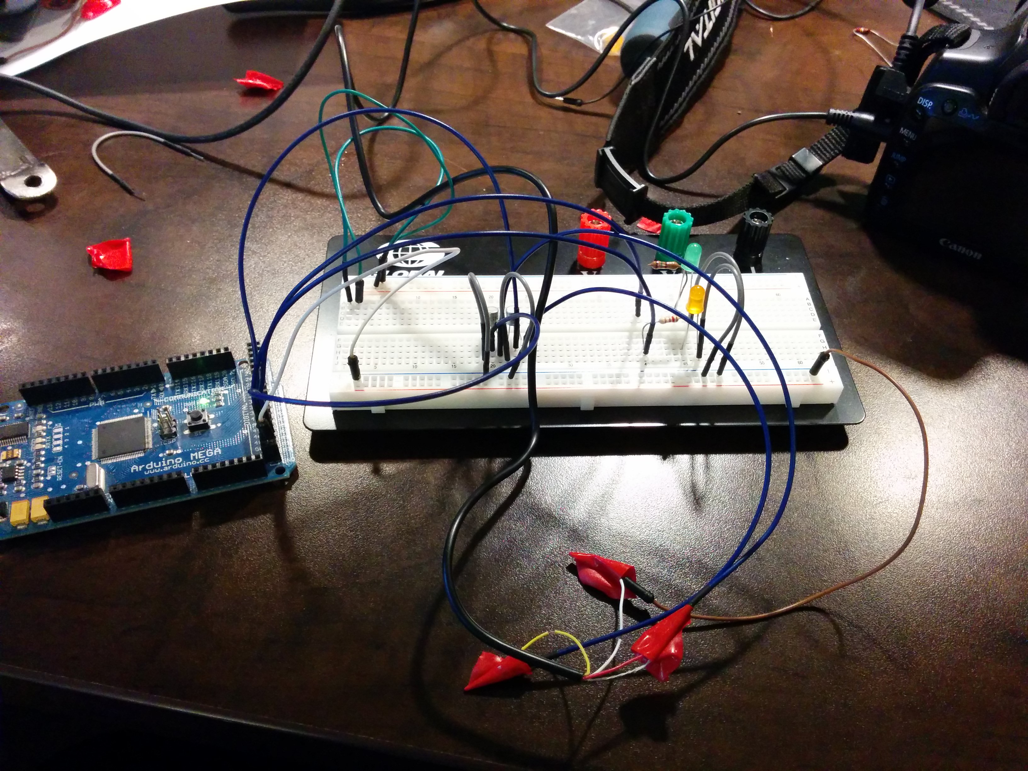
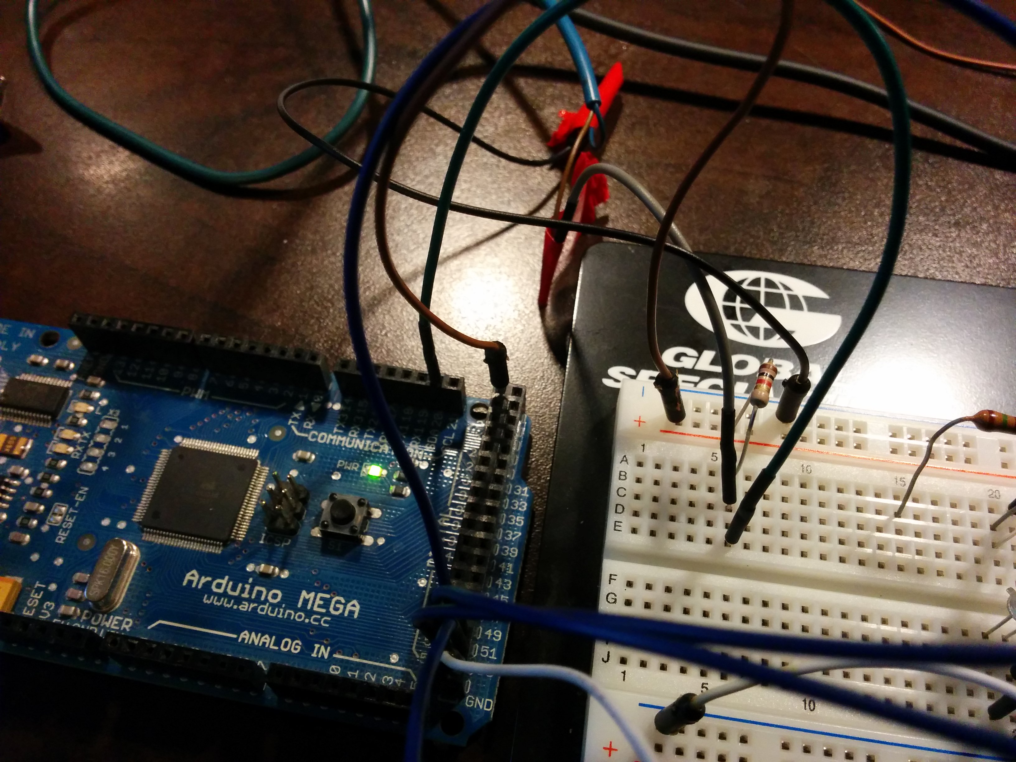
Here's my breadboard and stuff:
Download source code/project files (just arduino code)
The end result of this test is that I can trigger the camera to take a picture after a proximity sensor receives 10 pulses.
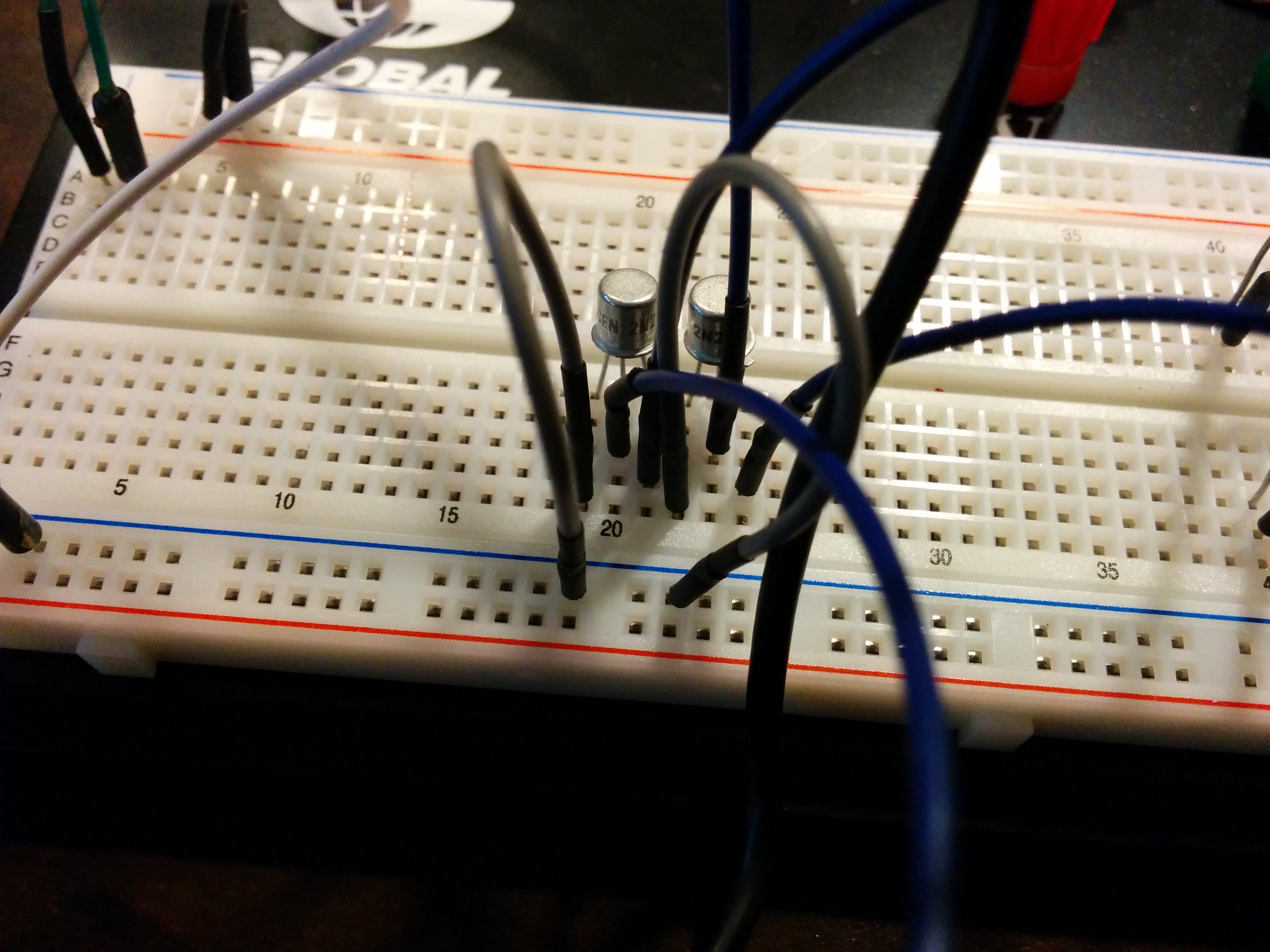
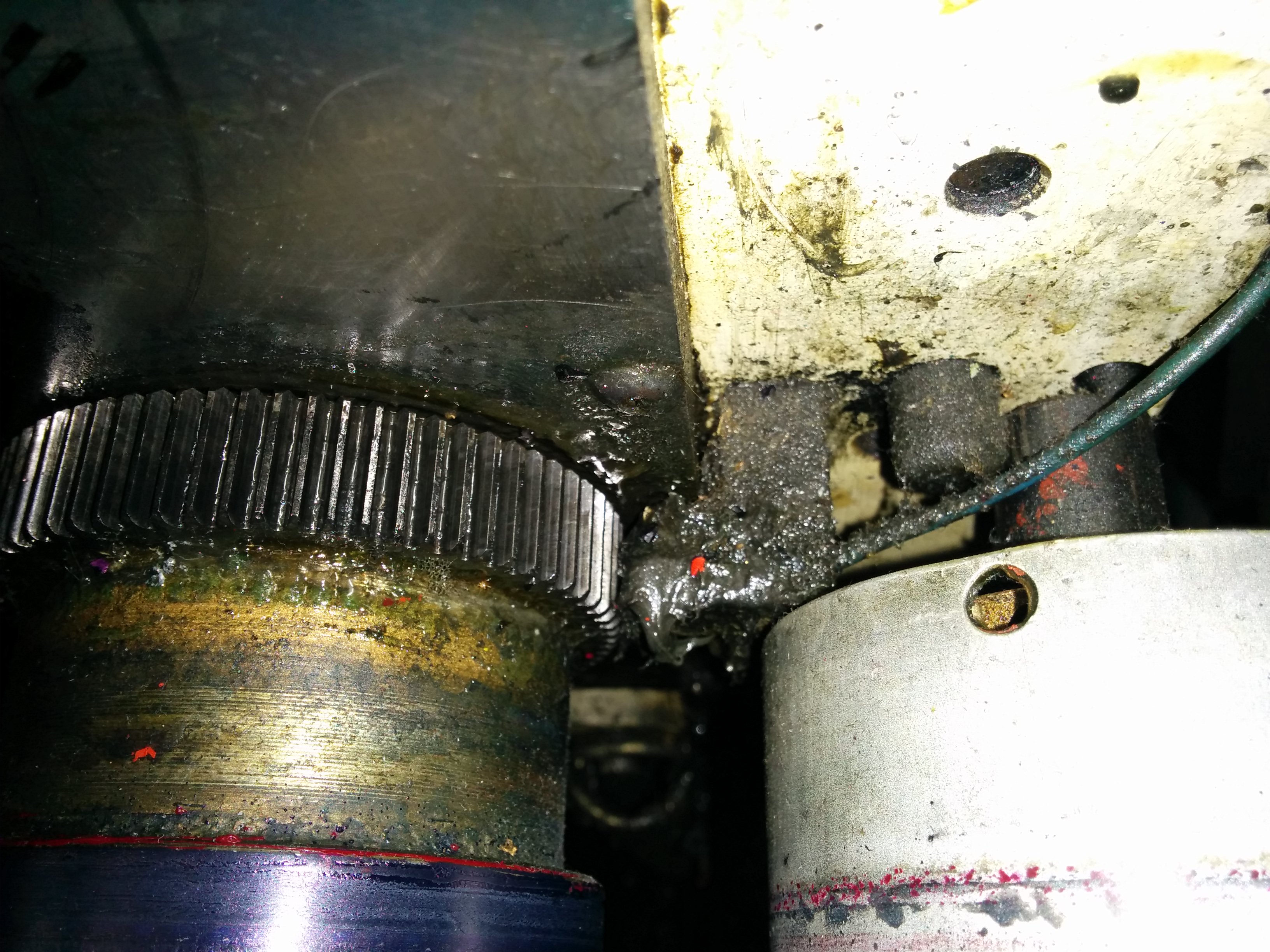
First of all, let's meet our sensor. It's a proximity sensor used on Mark Andy 4200 printing presses for re-registering print. They're located on each print station on the press. There are two wires coming from it, blue and brown. Blue is the ground. In this circuit, we have 5V coming from the Arduino into a 1k resistor which then splits out into two directions. One into the sensor, and another in pin 20 (marked "SDA 20" on the Arduino Mega). Pin 20 is the Mega's interrupt pin 3.
The Arduino code has changed a fair bit. In setup() I call attachInterrupt(3, pulse, CHANGE) ... this sets up interrupt pin 3, calls the function "pulse" for each interrupt, and triggers the interrupt on any change - falling or rising. My father and I found that by decreasing the resistance in this circuit we could decrease the sensitivity of the proximity sensor. When we used a 4.7k resistor, the sensor was much too sensitive and would continue counting even when you held it stationary above a piece of metal. Using a 1k resistor worked much better, although I'm still not sure if it is what I will settle on in the finished product. I really need to test it in a real-world situation.
Anyways, every time the voltage changes (as it does when it comes in close contact with a piece of ferrous metal) it triggers pulse(). pulse() turns on the focus LED, which is a bit confusing because I was just using that pin for testing purposes to know that the sensor was working properly. It then increases the counter and prints that value. When the counter reaches a specific goal - a tooth size of 10 in this example - the code used in case 's' in the previous example is used. Herein lies the limitation with this code - I have to detach the interrupt in order to prevent the interrupt from stopping the camera from taking a picture, otherwise the whole process of taking the picture is interrupted by the interrupt when another pulse is picked up! This in turn means that the code is no longer counting the teeth on the gear, so you lose your place. Every 10T is not going to be every 10T. It'll be 10T, picture taken while the gear is still turning, and then another 10T starting from a different location. Not very helpful for a camera designed to watch one specific area of a label on a press!
The solution seems to be that we need 2 arduinos running at once. One purely for counting teeth, and another that can handle taking the picture with the camera. Happily, my father has a second arduino and this should be possible! I think all the code is there, we just have to divide it up between the two boards. It is also important to note that I do not use my C# code at all in this example - everything here runs using just the arduino code. The C# will be important later for inputting the desired tooth size, as it will change from job to job. Here is a picture of the circuit in question in this example, but the code is the real winner here! Finally, here is the Arduino code!
#define FOCUS_PIN 51
#define FOCUS_LED 50
#define SHUTTER_PIN 53
#define SHUTTER_LED 52
#define SENSOR_PIN 49
//#define TEST_PIN 45

int counter = 0;
int tooth = 10;

//ISR
void pulse()
{
  digitalWrite(FOCUS_LED, HIGH);
  //delay(1000);  // doesn't work in an ISR!
  digitalWrite(FOCUS_LED, LOW);
  counter++;
  Serial.println(counter);

  if(counter == tooth)
  {
	detachInterrupt(3);
	digitalWrite(SHUTTER_PIN, HIGH);
	delay(2000); // May want to adjust this depending on shot type
	digitalWrite(SHUTTER_PIN, LOW);
	digitalWrite(SHUTTER_LED, HIGH);
	delay(1000);
	digitalWrite(SHUTTER_LED, LOW);
	attachInterrupt(3, pulse, CHANGE);
  }

}

void setup()
{
  pinMode(FOCUS_PIN, OUTPUT);
  pinMode(SHUTTER_PIN, OUTPUT);
  digitalWrite(FOCUS_PIN, LOW);
  digitalWrite(SHUTTER_PIN, LOW);
  pinMode(FOCUS_LED, OUTPUT);
  pinMode(SHUTTER_LED, OUTPUT);
  pinMode(SENSOR_PIN, OUTPUT);
  attachInterrupt(3, pulse, CHANGE);
  Serial.begin(9600);
}

//Loop() omitted because it doesn't do anything in this example!
Download the Arduino/ATTiny85/C# source code
There's a bit of a gap between this step and the previous one! I had a bunch of obstacles to overcome before the first real-life test on a press. The biggest hurdle was learning to program an ATTiny85 - see this link here for a tutorial! I wanted this chip to run the camera shutter while the Arduino ran the proximity sensor.
Because we're using an older DSLR camera for this project, we only have an RCA video output. Luckily, we had an old TV that would be perfect. Unfortunately, you need the remote to change the video mode on this particular TV, and my father forgot it at his property in the U.S.! We got around this issue the next day by bringing in a universal remote we had collecting dust in the basement, but I ended up using a projector to test the camera display this first day, which was actually pretty cool! I wish I had taken a picture of this first setup!
Here were the issues I found and fixed in version 0.7:
- When you reset the count to be a number less than the number the counter variable is already at, the counter variable never reaches its target to reset. I fixed this in 0.7 by resetting the counter variable when the target tooth count is changed.
- Input loops from the C# program - if you clicked "advance", for example, it's supposed to subtract a tooth from the counter variable to move the camera's next shot back by a gear tooth. The problem is that it kept subtracting a tooth every Loop()! I fixed this in 0.7 by creating a new function in the C# program called sendToArduino that opens the serial port, sends the data to the Arduino, waits 900ms (Thread.Sleep(900);), and then closes the serialport. This version of the C# program (0.6) just opens the serial port after you select COM3 (or whatever you're using) and closes it upon the form closing.
- Getting delays and interrupts to work together. I know this is sort of a taboo in the Arduino community, but here's the problem. I want the tooth counts to be part of an interrupt, but I want the camera to have a cooldown of 7 seconds so the it doesn't get overloaded by taking pictures too frequently. This is definitely a limitation of using a DSLR with flash (we will need to add an external flash later, that's for sure!). Delay() and interrupts do not play together nicely - interrupts just interrupt the delays! In the end I ended up using millis() in the attiny85 code to help act as a timer, and when certain times were reached the program would react. For example, if time - lastCycle (time is millis() and lastCycle is the last time a picture taking opportunity occurred) is greater than the cooldown time (7 seconds), the pin for the shutter can be set to HIGH. 2 seconds after that, it is set to LOW. And if time - lastCycle is less than the cooldown time, the shutter pin cannot be set to HIGH!
- To get around the above problem with the camera cooldown, I had a "multiplier" feature. So, for example, if you were running a 66 tooth job with a multiplier of 5, the program would take a picture every 330 teeth. The problem with this is that 1) it's sloppy 2) it's not very user friendly 3) you run into issues at high press speeds - the tooth target is really high, and 4) the multiplier multiplies the effects of the advance/retards, making them difficult to use at higher multiplier values. Happily I was able to ditch the multiplier in version 0.7.
There is no other way to say this - this project ended up being extremely easy once I decided to come back to it a few months later with a bit more Arduino experience under my belt! And, more importantly, a better proximity sensor. I ended up buying this sensor here, and everything fell into place once I replaced that crappy old 80s Mark Andy prox sensor with that one!! Also, the ATTiny85 was completely unnecessary, and once I discovered how millis() could be used as a timer to make a sort of "psuedo-delay" I came back to this project, scrapped most of the original code, and came up with this simple sketch below.
//FLEXO CAMERA
//r.lagserv.net

//Variables we actually want control over
float interval = 5000;  //in milliseconds
volatile int teethTarget = 88;
int shutterPin = 11;

//Initialize global variables
volatile long int c = 0;
unsigned long totalTimeElapsed = 0;
unsigned long previousTimeElapsed = 0;

//------------------------------------------------------
//ARDUINO SETUP
//------------------------------------------------------
void setup()
{
  //Disable SD card if one in the slot
  pinMode(4,OUTPUT);
  digitalWrite(4,HIGH);

  //Setup shutter pin
  pinMode(shutterPin, OUTPUT);
  digitalWrite(shutterPin, HIGH);

  //Setup interrupt for counting gear teeth
  attachInterrupt(digitalPinToInterrupt(3), pulse, FALLING);

  //Begin serial
  Serial.begin(115200);
}

//------------------------------------------------------
//MAIN ARDUINO LOOP
//------------------------------------------------------
void loop()
{
}

//------------------------------------------------------
//PULSE FUNCTION (ISR) - COUNTS GEAR TEETH
//------------------------------------------------------
void pulse()
{
  //Make sure the camera is off!
  //digitalWrite(shutterPin, LOW);

  //Increment the counter variable
  c++;

  Serial.println(c);

  //Check to see if it's time to take a picture!
  if(c == teethTarget)
    TakePicture();

  totalTimeElapsed = millis();

  if(totalTimeElapsed - previousTimeElapsed > 2000)
    digitalWrite(shutterPin, HIGH);
}

//------------------------------------------------------
//TAKEPICTURE - Trigger the camera shutter!
//------------------------------------------------------
void TakePicture()
{
  //Get the total time the program has been running
  totalTimeElapsed = millis();

  //When the interval has elapsed we are okay to take another picture. Don't want to overload the camera!
  if(totalTimeElapsed - previousTimeElapsed > interval)
  {
    //Reset the time
    previousTimeElapsed = totalTimeElapsed;

    //Take a picture!
    digitalWrite(shutterPin, LOW);
    Serial.println("Picture taken!");
  }

   //Reset the teeth count
    c = 0;
}
I kept the ISR to count gear teeth and used millis() as a timer to make sure the camera shutter doesn't fire too quickly that the DSLR we were using got overwhelmed. The circuit was simpler as well - I ditched the transistors I was using and connected the red shutter wire directly to the shutter pin listed in the sketch, the ground directly to ground, the power directly to the 5V out from the Arduino. Super simple! And it works! It works really well, actually! The only real problem with this version is that in order to change the tooth size from job to job you have to reupload the sketch. In addition, you cannot advance/retard the camera to move it around the label on press - but these are all pretty easy things to add with the knowledge I have gained from my father's and my 4200 "operating system" project. Hopefully I will get to making an interface soon and will update the sketch accordingly!